
Home automation with Home-Assistant and Raspberry Pi Zero – Part 2: Wiring
In my first blog post on Home Automation I published a list of parts needed for building the hardware. Yes I know…. you need a tutorial showing you how to assemble the parts. So here it is – heat up your soldering iron!
Schematics
This is a schematic of how i connected the different hardware parts to the Raspberry Pi Zero. Note that both the 433 MHz Receiver and Transmitter should have an antenna. If the receiver is only needed for the purpose of learning the 433MHz remote commands you can omit the antenna and just hold the remote very close (approximately 1-5cm to it). You should be able to use a wire of 17cm length as an antenne but I would recommend buying the one mentioned in the first post.

- 433MHz Receiver
- VCC – 5V (Header 2)
- DATA – GPIO27 (Header 13)
- GND – GND (Header 6)
- ANT – Antenna
- 433MHz -Transmitter
- DATA – GPIO17 (Header 11)
- GND – GND (Header 6)
- VCC – 5V (Header 2)
- ANT – Antenna
- NPN-Transistor
- GPIO20 (Header 38) with preceding10k Ω resistor
- GND (Header 6)
- Last LED cathode
- LEDs
- Series connection
- preceding 20Ω resistor (calculate the correct level)
- Connected to transistor
- IR Receiver
- 3,3V (Header 1)
- GND (Header 6)
- GPIO23 (Header 16)
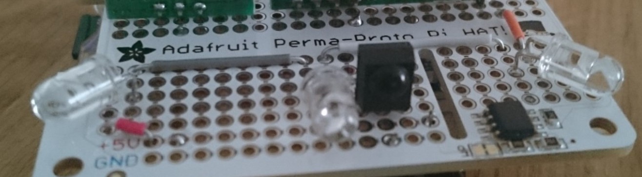
The finalized Perma-HAT

In my next blog post I am going to show you how to install the software… stay tuned!